- Home
- /
- BSS Design Awards for...
BSS Design Awards for 2021 to 2025
The British Sundial Society announces its seventh Awards Scheme for Excellent Sundials.
The only requirement is that the dials must have been made or restored between January 2021 and December 2025 inclusive; otherwise this scheme is open to all-comers. Entries in the form of one or more photographs and a brief description are invited from amateurs, professionals, members and non-members, from the UK and overseas. Awards (in the form of certificates) will be made for new sundials and for sundial restoration projects.
Please submit entries as emails and attachments to designawards@sundialsoc.org.uk. Please include the name of the maker or organization and the location of each sundial. For a dial that is private or vulnerable, specifying an approximate location is permitted.
Entries will appear on the BSS website. Items submitted are subject to moderation. Selected entries will be exhibited at the 2026 BSS conference.
Four examples submitted last time are shown below. The Society particularly welcomes entries from schools and colleges, so please encourage any school or college that you think might be interested.
Anton Leach and David Hawker
designawards@sundialsoc.org.uk
Here are the current entries, in order of date received.
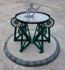
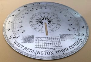
The Bedlington Terrier Dial
Tony Moss
Tony Moss submitted this entry as his very last sundial. The dial was created over three years. The design work was completed using Adobe illustrator and the fabrication was done by Barrington Metalworks locally. The sundial celebrates the local coal mining history as well as the local famous dog.
The Town Council finally accepted the dial on 7 December 2021. The inauguration was in the presence of dignitaries and was followed by lunch
The sundial was featured on the front cover of the Bulletin and there was an associated article.


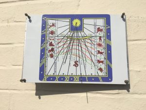
Replica of The Queen's dial at Cambridge
Sean Clarke
Sean writes:
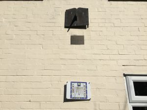
This is a 1:10 scale working replica of The Queen's dial at Cambridge.
The house wall declines 5.2 deg to the east. The Cambridge dial declines 13 deg to the east.
My replica' declination can be adjusted to tweak the final setting.
The sub style angle to the south line is calculated as 10.04 deg to the west. The style angle to the table is 37.05 deg. The latitude of my location is 51.79 deg N (Cuddington, Buckinghamshire).
My replica is a print on thin aluminium plate. The picture was taken on 12 March 2025 and the nodus shadow can be seen on the straight equinox line.
For such an aesthetically pleasing sundial it was surprising easy to construct. Fortunately, Queen's College, Cambridge have produced a JPEG image on their website (see below) that is free to use for personal use. The down loaded file was presented to one of a myriad of printers (many on eBay) who can print any image onto thin aluminium plate for about £10-£20.
The printed image was carefully glued onto a rigid piece of aluminium plate and four holes (5mm) drilled in each corner. A fifth hole, for placement of the style (1mm brass rod), was also drilled through the plate. To achieve the correct angle the style makes to the plane of the dial (table). 10mm of one end of thin round rod was gently clamped into a workbench vice such that the rest of the rod protruded exactly vertical While still clamped the rod was carefully bent over until the desired angle was found (previously calculated), measured with a protractor with respect to the horizontal.
The style rod was carefully glued into the correct position with a metal adhesive and oriented to the required angles (previously calculated for my local circumstances) using a protractor and set square. After the glue had set there was sufficient movement in the rod to refine the style's orientation.
The nodus was simply a common gold coloured bead with a pre drilled hole of diameter equal to style's thickness. The bead was glued into position on the style such that it sits directly above the dials horizon line.
Two length of flat metal bar (brass) were tapped to accept four lengths of short 4mm threaded rod. These flat bars (with attached threaded rods) were carefully positioned and attached to the wall such that the 4 holes in the sundial plate could pass along the threaded rod allowing some tilt and importantly, that the bottom and top edges of the dial were horizontal. There are two locking nuts on each threaded rod so the dial can be locked into place.
The calibration of the dial with the actual sky was achieved by first loosening the 8 locking nuts of the threaded rod (4 behind and four in front) so the dial had some freedom of movement. An arbitrary apparent local solar time was chosen (i.e 1100 hrs) and the dial later locked down when my chosen local solar time equalled the calculated mean zone time (UTC), all this taking into account longitude and the equation of time.
My advice for anyone wanting to produce their own dial is to check with their chosen printer how stable their inks are under prolonged UV exposure - some fade faster than others.